


Design & Operating Conditions – Equipment must not be operated at conditions which exceed those
specified on the name plate(s).
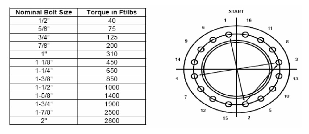
Bolted Joints – Heat exchangers are pressure tested at JFD’s facility in accordance with ASME Code requirements. However, normal relaxing of the gasketed joints may occur in the interval between testing and installation at the job site. Therefore, all external bolted joints should be properly retightened (see diagram on page 8) after installation, and again after the unit has been heated. This is to prevent leaks and gasket blowout.
Start-Up Operation – When placing a unit in operation, open all vent connections and start to circulate the cold media only. Be sure the cold side of the unit is entirely filled with fluid before closing the vents. The hot media should then be introduced gradually until all passages are completely filled with liquid or vapor, whichever the case may be. Then close the vents and slowly bring the unit(s) up to temperature.
Start operation gradually. Do not subject the heat exchanger to sudden temperature fluctuations. Hot fluid must not be suddenly introduced when the unit is cold, or vice-versa. This could damage the exchanger and void the warranty.
For Fixed Tube Sheet units, fluids must be introduced in a manner to minimize differential expansion between the shell & the tubes.
Shut-Down Operation - For U-Tube and Floating Rear Tube Sheet units, flow of the hot media should be gradually shut off first. If it is necessary to stop the circulation of the cold media, the circulation of the hot media should be stopped also, through bypassing or other means. For Fixed Tube Sheet and Double Tube units, the unit should be shut down in a manner to minimize the differential expansion between the shell & tubes.
Drain all fluids when shutting down to eliminate the possibility of freezing and/or corrosion. To guard against water hammer, condensate should be drained from units using vapors during start-up or shutdown.
For Fixed Tube Sheet units, the tube-side may require blowing out with air to minimize water retention after drainage.
***Caution***
Steam and/or water hammer can cause serious damage to the tubes of any heat exchanger. A careful consideration of the following points before an installation is made can prevent costly repairs which may be required due to hammer.
1. With Heat Exchanger completely assembled, remove ½’’ and ¾’’ MPT plugs from sight indicator and vent connections. These connections should be at the highest point in relation to the heat exchanger shell.
2. Fill the ¾’’ FNPT connection with 100% Ethylene Glycol. The ½’’ connection acts as a vent.
3. Let stand 30 minutes.
4. Install sight window in the ¾’’ FNPT connection. Then top off with glycol through the ½’’ connection. Vent remaining air by gradually turning on the hot-side media. Once all air has vented out, and glycol begins to bubble out, tighten ½’’ FNPT connection and plug. Then gradually introduce the cold-side media, and bring the unit(s) up to temperature.
Bolted Joints – Heat exchangers are pressure tested at JFD’s facility in accordance with ASME Code requirements. However, normal relaxing of the gasketed joints may occur in the interval between testing and installation at the job site. Therefore, all external bolted joints should be properly retightened (see diagram on page 8) after installation, and again after the unit has been heated. This is to prevent leaks and gasket blowout.
Start-Up Operation – When placing a unit in operation, open all vent connections and start to circulate the cold media only. Be sure the cold side of the unit is entirely filled with fluid before closing the vents. The hot media should then be introduced gradually until all passages are completely filled with liquid or vapor, whichever the case may be. Then close the vents and slowly bring the unit(s) up to temperature.
Start operation gradually. Do not subject the heat exchanger to sudden temperature fluctuations. Hot fluid must not be suddenly introduced when the unit is cold, or vice-versa. This could damage the exchanger and void the warranty.
For Fixed Tube Sheet units, fluids must be introduced in a manner to minimize differential expansion between the shell & the tubes.
Shut-Down Operation - For U-Tube and Floating Rear Tube Sheet units, flow of the hot media should be gradually shut off first. If it is necessary to stop the circulation of the cold media, the circulation of the hot media should be stopped also, through bypassing or other means. For Fixed Tube Sheet and Double Tube units, the unit should be shut down in a manner to minimize the differential expansion between the shell & tubes.
Drain all fluids when shutting down to eliminate the possibility of freezing and/or corrosion. To guard against water hammer, condensate should be drained from units using vapors during start-up or shutdown.
For Fixed Tube Sheet units, the tube-side may require blowing out with air to minimize water retention after drainage.
***Caution***
Steam and/or water hammer can cause serious damage to the tubes of any heat exchanger. A careful consideration of the following points before an installation is made can prevent costly repairs which may be required due to hammer.
- A vacuum breaker and/or vent should be used in accordance with the type of system being installed.
- The proper trap for a steam system installed should be used.
- The trap and the condensate return line to the trap should be properly sized for the total capacity of the unit(s).
- The trap should be sized for the differential pressure across the trap, not the inlet pressure to the steam controller.
- A properly sized relief valve must be installed on the heated water side to protect the heat exchanger(s) from possible damage due to volumetric expansion.
- In the case of steam as the heating medium, the steam trap should be manually by-passed until the exchanger is switched to automatic operation. Water hammer often results when a large quantity of steam is allowed to condense rapidly in an enclosure. This usually happens when the demand for hot water ends and the steam control valve closes, but there is still substantial steam left in the exchanger. As this steam condenses, the pressure drops (often to full vacuum). This prevents condensate from leaving the shell and sometimes siphons in condensate from a line beyond the trap. Now, when steam valve opens again and admits steam to the shell, the rapid condensation, as it strikes the cold condensate left in the shell, causes streams of water to rise, hitting the top of the shell and bouncing onto the top of the tubes.
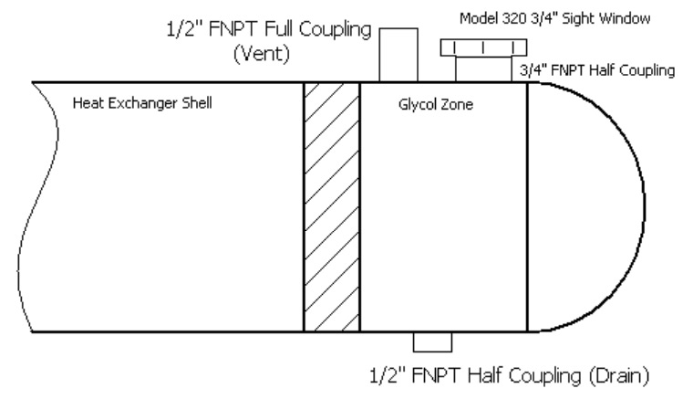
Recommended Procedure for Flooding Intermediate Zone with Glycol in Double Tube Safety Heaters
1. With Heat Exchanger completely assembled, remove ½’’ and ¾’’ MPT plugs from sight indicator and vent connections. These connections should be at the highest point in relation to the heat exchanger shell.
2. Fill the ¾’’ FNPT connection with 100% Ethylene Glycol. The ½’’ connection acts as a vent.
3. Let stand 30 minutes.
4. Install sight window in the ¾’’ FNPT connection. Then top off with glycol through the ½’’ connection. Vent remaining air by gradually turning on the hot-side media. Once all air has vented out, and glycol begins to bubble out, tighten ½’’ FNPT connection and plug. Then gradually introduce the cold-side media, and bring the unit(s) up to temperature.